Categories
GEOMETRIC DIMENSIONING AND TOLERANCING

Tolerancing 0ptimization Strategy #2 (Combination of Linear and Geometric)
Tolerancing 0ptimization Strategy #2 (Combination of Linear and Geometric)

TOLERANCING 0PTIMIZATION STRATEGY #2 (COMBINATION OF LINEAR AND GEOMETRIC)
Linear And Geometric Dimensioning And Tolerancing Boundary Example

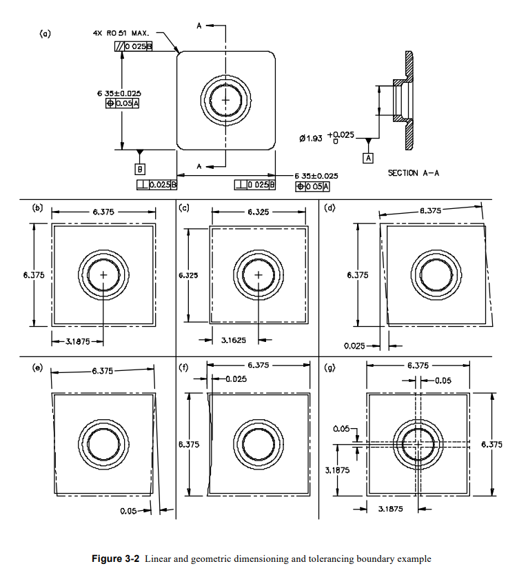
Fig. 3-2a is a combination of linear and geometric callouts, and clearly adds controls for orientation of one surface to another. This is achieved with perpendicularity callouts on the left and right sides of the part in relationship to datum -B-, along with a parallelism callout on the top of the part, also to datum -B-. In addition, position callouts were added to each of the size dimensions (6.35 mm ±0.025 mm) and were controlled in relationship to datum -A-, which is the “axis” of the inside diameter (1.93 mm +0.025 mm /–0 mm).
Figs. 3-2b to 3-2g define some of the conditions allowed by these drawing callouts.

Fig. 3-2b shows a part perfectly square and made to its maximum size based on the specification (6.375 mm), which would be an acceptable part for size. Assuming the hub was exactly in the center where
the designer would like it to be, this part would measure 3.1875 mm. Unlike the negative impact mentioned in regards to Fig. 3-1b, this measurement adds no negative impact to specifications because the “center plane” is now being located from the “center” of the inside diameter.

Like Fig. 3-2b, Fig. 3-2c shows a part that is perfectly square and made to its minimum allowable size based on the specifications (6.325 mm), which is again acceptable for size. Again, assuming the hub was
exactly in the center where the designer would like it to be, the 3.1625 mm measurement has no negative impact on specifications.

Fig. 3-2d (like Fig. 3-1d) shows a part on the large side of the tolerance allowed, with its orientation skewed to the shape of a parallelogram. In this example, however, the perpendicularity callouts added in
Fig. 3-2a control the amount this condition can vary. In this case it is 0.025 mm. The problem that stands out here is that the designer’s original intent stated: to have the external boundary utilize a space of 6.35mm ±0.025 mm “square.” Based on this requirement, it’s clear this objective was not met. Granted, it is controlled tighter than the requirements defined in Fig. 3-1a, but it still does not meet the designer’s expectations.

Fig. 3-2e shows a combination of Figs. 3-2b and 3-2c (like Figs. 3-1b and 3-1c), in that it allows the shape to be small at one end and large at the other. Unlike Figs. 3-1b and 3-1c, Fig. 3-2e restricts the
magnitude of change from one end to the other by the parallelism and perpendicularity callouts shown in Fig. 3-2a.

Because this part is symmetrical, a unique problem surfaces in this example. Using Fig. 3-2e, assuming the bottom surface is datum -B-, the top surface is shown to be perfectly parallel. Due to the part being
symmetrical, it is impossible to determine which surface is truly datum -B-. So, if we assume the left-hand edge of the part as shown in Fig. 3-2e was the datum, the opposite surface (based on the shape shown)
would show to be out of parallel by 0.05 mm.

This clearly shows that problems in the geometric callouts are not only in the design area, but also in the ability to measure consistently. Like-type parts could measure good or bad, depending on the surface identified as datum B
Fig. 3-2f again shows displacement in shape allowed. In this case it shows a part that is for the most part large, except all the variability (0.025 mm) shows up on one edge. The limiting factor (depending on
which surface is “chosen” as datum -B-) is the perpendicularity or parallelism callouts.
Fig. 3-2g is showing a part made to its large size (like Fig. 3-1b), and the 0.05 mm zone allowed by the position callout. Unlike Fig. 3-1g, the larger or smaller size of the square shape has no impact on the
position. Based on the callout in Fig. 3-2a, the center planes (mid-planes) in both directions must fall inside the dashed boundaries.

The above comments concerning Fig. 3-2a are intended to show a tolerancing strategy that encompasses both liner and geometric callouts but still does not meet the designer’s intended expectations. Based on this, the designer modified the drawing again, as shown by Fig. 3-3a, which led to strategy #3.

Tolerancing 0ptimization Strategy #3 (Fully Geometric)
TOLERANCING 0PTIMIZATION STRATEGY #3 (FULLY GEOMETRIC)
Fully Geometric Dimensioned And Tolerance Boundary Example

Tolerancing 0ptimization Strategy #3 (Fully Geometric)

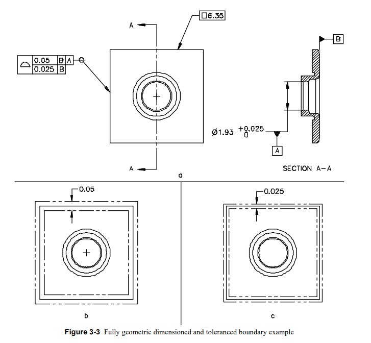
Fig. 3-3a is the optimum dimensioning and tolerancing strategy for this design example. In this case, the outside shape is defined clearly as a square shape that is 6.35 mm “basic,” and is controlled with two
profile callouts. The 0.05 mm tolerance is shown in relationship to datums -B- and -A-, controlling primarily the “location” of the hub in relation to the outside shape (depicted by Fig. 3-3b). The 0.025 mm tolerance is shown in relationship to datum -B- and controls the total variation of “shape” (depicted by Fig. 3-3c).
This tolerancing strategy clearly defines the designer’s intent.

Link for Tolerance Optimization Strategy 1
https://udhasulnayakblog.com/tolerancing-optimization-strategies-design/

Link for General Motor Engine Assembly line LM-850
https://youtu.be/fjCf9jXXp0o

Check link for Tolerance Stack Up Analysis
https://youtu.be/0LVnLDltRC0

Categories
GEOMETRIC DIMENSIONING AND TOLERANCING

Tolerancing 0ptimization Strategies in Industry

  1. Tolerancing Methodologies in Industry.
    This chapter will give a few examples to show the technical              advantages of transitioning from linear dimensioning and tolerancing methodologies to geometric dimensioning and tolerancing methodologies.
    The key hypothesis is that geometric dimensioning and tolerancing strategies are far superior for clearly and unambiguously representing design intent, as well as allow the greatest amount of tolerance.
  2. Tolerancing Progression (Example #1)Strategy #1 (Linear)

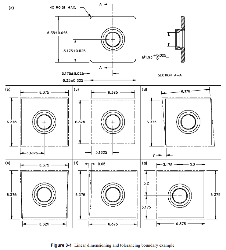
    Fig. 3-1a represents the original dimensioning and tolerancing strategy that is strictly linear. In this figure,the outside shape in the vertical and horizontal directions is 6.35 mm ±0.025 mm, while the hub is located at half the distance of the nominal width from the center of the part. Section A-A shows the allowable
    variation for the inside diameter.
    It clearly indicates Fig. 3-1a to be lacking at least some geometric controls or at a minimum some notes to identify the degree of orientation and locational control. Figs.3-1b to 3-1g show a few of the possible combinations of part variability (represented by dashed lines) that are allowed by the current “linear” callouts.
    Fig. 3-1b shows a part perfectly square and made to its maximum size based on the tolerance specification (6.375 mm), which would be an acceptable part for size. Assuming the hub was exactly in the center.
    where the designer would like it to be, this feature would measure 0.0125 mm off its ideal location based on this part’s large size. Ideal nominal was 3.175 mm, and the actual value measured was 3.1875 mm, which would be a displacement of 0.0125 mm. It meets intended ideal, but fails specified ideal.
    Like Fig. 3-1b, Fig. 3-1c shows a part that is perfectly square but is now made to its minimum allowable size based on specification (6.325 mm), which is again acceptable for size. Assuming the hub was exactly in the center where the designer would like it to be, this part also would measure 0.0125 mm off its ideal location based now on the part’s small size. The ideal nominal was 3.175 mm, and the actual value measured was 3.1625 mm, which also shows a displacement of 0.0125 mm. Again, it meets intended ideal, but fails specified ideal.

    LINEAR DIMENSIONING AND TOLERANCING BOUNDARY EXAMPLE
    Linear Dimensioning And Tolerancing Boundary Example

    “the limits of size do not control the orientation.” Fig. 3-1d
    describes the condition that can occur based on the lack of geometric control for orientation. In this example, the part is restricted to the shape of a parallelogram, and the degree allowed is questionable. This particular example clearly shows the designer’s intent would not be met if this condition was accepted.
    Based on the drawing callouts currently defined, it could not be rejected.

    Fig. 3-1e shows a combination of Figs. 3-1b and 3-1c where it allows the shape to be small at one end and large at the other. Fig. 3-1f takes this one step further and shows a part that is, for the most part, large, except all the variability (0.05 mm) shows up on one edge.

    Fig. 3-1g is showing a part made to its large size (like Fig. 3-1b), and the hub shifted off the “designer’s ideal” center, so it is centered on its nominal dimension. This figure also shows the effect this would have on its opposing corner which would be a displacement out to its worst-case tolerance of +0.025 mm
    (3.2 mm). The more challenging part would be to determine which edge is being measured, from one part to the next. This is somewhat difficult to do on a part that is designed perfectly symmetrical.

    Link to check Perpendicularity Tolerancing
    https://youtu.be/R9YePJFxg0E

    Link to view Metal can Producing
    https://youtu.be/8it1gxFGQPE

    check link for GD&T
    https://udhasulnayakblog.com/geometric-dimensioning-and-tolerancing-design/

    Check link for Tolerance Stack Up Analysis
    https://youtu.be/0LVnLDltRC0
Categories
Form Tolerance

Circularity

Circularity Tolerance

TOLERANCE
Circularity Tolerance

Circularity Tolerance 
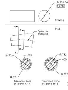
A circularity tolerance controls a feature’s roundness at individual cross sections. Thus, a tolerance may be applied to any type of feature having uniformly circular cross sections,

The tolerance zone plane shall be swept along a simple, nonself intersecting, tangent-continuous curve (spine). At each point along the spine, the tolerance zone plane shall be perpendicular to the spine and the tolerance zone centered on the spine.

As the tolerance zone plane sweeps the entire feature surface, the surface’s intersection with the plane shall everywhere be contained within the annular tolerance zone (between the two circles). While sweeping, the tolerance zone may continually adjust in overall size, but shall maintain the specified radial width.

This effectively removes diametral taper from circularity control. Additionally, the spine’s orientation and curvature may be adjusted within the aforementioned constraints. This effectively removes axial straightness from circularity control. The tolerance zone need not be concentric with either size limit boundary.

TOLERANCE TO SPHERICAL FEATURE
Circularity Tolerance To Spherical Feature

A  tolerance greater than the total size tolerance has no effect. The tolerance between the full size tolerance and one-half the size tolerance limits only single-lobed (such as D-shaped
and egg-shaped) deviations.
The tolerance must be less than half the size tolerance to limit multilobed (such as elliptical and tri-lobed) deviations.

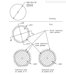
Circularity Tolerance Applied to a Spherical Feature.
The tolerance specifies a tolerance zone bounded by two concentric spheres whose radii differ by an amount equal to the tolerance value. The tolerance zone may adjust in overall size, but shall maintain the specified radial width.
All points on the considered spherical feature shall be contained within the tolerance zone (between the two spheres).
Since the tolerance zone need not be concentric with either size limit boundary, a circularity tolerance must be less than half the size tolerance to limit multi-lobed form deviations.

Please follow below link for Straightness Tolerance
https://udhasulnayakblog.com/straightness/

Video Explaining Perpendicularity
https://youtu.be/JScvHJTToWA


Categories
Form Tolerance

Straightness Tolerance

Straightness Tolerance

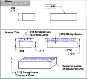
Straightness is a condition where an element of the surface or axis is a straight line. Tolerance is applied in the view where the element is controlled are represented by a straight line.
For the illustration below, the tolerance zone is oriented longitudinally and located in the two highest areas along the measuring surface location. All the elements along that location must be fallen between two tolerance line boundaries.

TOLERANCES
Straightness Tolerance
STRAIGHTNESS TOLERANCE
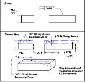
Straightness Per Unit Length Basis.
Straightness Tolerance per unit basis.

Straightness may be applied per unit basis. The surface’s straightness per unit length specified length shall not vary more than the specified unit length straightness tolerance.
For example – The tolerance lines are parallel to each other, displaced 0.001and oriented parallel with respect to the surface. The tolerance lines may overlap or be placed end-to-end.

Straightness Tolerance on surface(Cylindrical)

Each Longitudinal element of a cylindrical surface must lie between two parallel tolerance lines (0.010 apart) Where two lines and the nominal axis of the part share a common plane.
The cylindrical feature must lie within specified limits of size and meet  the requirement set forth by the envelope principal

STRAIGHTNESS OF SURFACE(CYLINDRICAL)
Straightness Of Cylindrical Surface
STRAIGHTNESS OF FEATURE OF SIZE
Straightness Of Feature Of Size @Mmc
VIRTUAL SIZE
Straightness Virtual Size

Straightness Tolerance of Feature of size @MMC

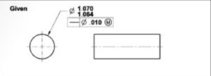
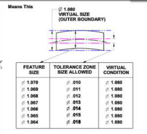
The tolerance is associated with a cylindrical size dimension specified at MMC. All circular elements of a cylinder surface must be within size limits.
The derived axis or centreline of the cylinder must lie within a cylindrical tolerance zone of 0.010 when the cylinder is produced at MMC size. As the size of the cylinder departs from MMC of size, the amount equal to that size departure is summoned to allow straightness tolerance. Virtual Condition is equal to the MMC condition of a cylinder plus the stated straightness tolerance.

Video Explaining Straightness.

https://udhasulnayakblog.com/wp-content/uploads/2021/10/Straightness-to-surface.mkv

Categories
Form Tolerance

Flatness

Flatness T0lerance

Flatness Tolerance is the condition of a surface where all elements are within one plane. It defines a tolerance boundary confined by two parallel planes within which all elements of the surface lie in between.
A condition of a surface having all elements in one plane.

FLATNESS DATUM CONDITION
Flatness

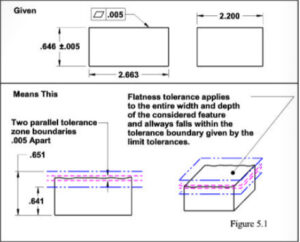
Tolerance shall be less than the total size tolerance variation. The tolerance boundaries are always contained within the specified limit of the size of tolerance boundaries.

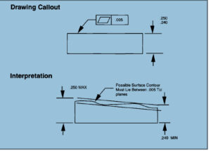
For example, as given below, the outer flatness boundary is oriented to the three highest locations of the upper surface. the inner boundary is maintained parallel and offsets to the outer flatness boundary by 0.005″ and all the elements of the surface must fall within outer and inner tolerance boundaries. Datum reference is not allowed since it only relates to the specific surface tolerance.

FLATNESS DRAWING CALLOUT
Flatness Drawing Callout
FLATNESS TOLERANCE APPLIED TO ENTIRE WIDTH AND LENGTH
Flatness Tolerance
Flatness Tolerance Applied to derived median Plan at MMC

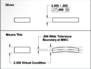
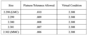
Tolerance may be applied on an RFS, MMC, or LMC basis to non-cylindrical features of size. In the example given in the figure, the measured or derived median plane must lie within the tolerance boundary consisting of two parallel planes at least as deep and wide as the feature of size, and the tolerance boundaries are separated by the amount of  tolerance specified (0.006) when the features of size are manufactured at MMC.

The feature-controlled frame must be clearly associated with the size tolerance or feature of size this application is not used with cylindrical features.


FLATNESS APPLIED TO MEDIAN PLAN AT MMC
Flatness At Mmc
FLATNESS TOLERANCE AND VIRTUAL CONDITION
Flatness Tolerance And Virtual Condition

https://udhasulnayakblog.com/straightness/